


You are here
SHRIMP history
History
SHRIMP has revolutionized geochronology allowing in situ U-Th-Pb analyses of U-bearing minerals in their petrological context. SHRIMP is often regarded as a zircon machine because of the productivity of the SHRIMP instruments in this area. However, SHRIMP is regularly used for stable isotope, isotopic anomaly, as well as trace element abundance measurements. This section deals with the development of SHRIMP, the geological ion microprobe.

SHRIMP allowed in situ dating of discrete zones in zircon. This
revealed for the first time the true complexities of the geochronology
of this mineral as well as its ability to record individual geological
events.
History - First generation
In the mid 1970s a revolution was taking place whereby chemical separation of rocks and minerals was being replaced by in situ analysis. Electron microprobes had been developed that allowed chemical compositions to be determined in minerals through the measurement of the intensity of chemical specific, characteristic X-rays. The electron probe performs well for major elements, but background radiation restricted the measurement of trace elements. The logical extension was the adoption of Secondary Ion Mass Spectrometry (SIMS) to allow measurement of low abundance elements.
The cornerstone of SIMS is the sputtering of material with a primary ion beam to produce a secondary ion beam. This ion beam can be analysed in a mass spectrometer for ionic abundance. Elemental abundances can be determined limited only by counting statistics. However, isotopic compositions can also be obtained. Decay of elements such as U and Th to Pb isotopes can be related to geological time.
The first ion microscopes were small instruments that had low sensitivity and low mass resolution. In order to carry out geochronological analyses, the abundance of 204Pb has to be accurately measured and the abundance of this isotope can be very low (attogram levels). The smaller ion microscopes could not carry out this measurement.

Ion microprobe mass analyser (IMMA)
manufactured by ARL., Sa. Barbara (1967)
History - Compston
The first ion microprobes were able to resolve individual unit masses, but could not deal with the complex molecular interferences produced in the sputtering process. Professor William Compston of ANU saw the solution to this problem in the design of a large ion microprobe capable of high mass resolution while maintaining high sensitivity. And so SHRIMP was born. Dr Steve Clement, an RSES graduate student who designed his own mass spectrometer for his PhD, was retained to design SHRIMP I based on ion optical parameters of Professor Hisashi Matsuda of Osaka University.

History - Matsuda design
Professor Hisashi Matsuda of Osaka University designed mass spectrometers with the goal of limiting aberrations to the total ion beam and maximizing sensitivity. Matsuda’s designs are based on cylindrical-geometry double-focussing mass spectrometers. The key element that he introduced was the use of quadrupole lenses to improve the phase-space matching between ion optical elements, notably between the ESA and magnet in SHRIMP II type designs. This accomplished high sensitivity in the mass spectrometer designs by allowing flexibility to maximize transmission in the Z (vertical) plane.
A mass spectrometer is generally defined by its mass resolving power and its sensitivity. The resolving power can be defined by the equation
R = C/(Xs + Δ + d)
Where s and d are the source and collector slit widths respectively, and C, X, and Δ the mass dispersion, the image magnification, and the total amount of image aberrations respectively.
Matsuda uses four main figures of merit for his designs. These are:
C/X, the ratio of mass dispersion to image magnification,
PF, the performance factor that includes elements of C/X, DLT, magnet deflection angle, and others,
AF, the aberration factor that is essentially the mass resolution of a minimal source and collector slit sizes, and,
DLT, the total distance along the path length.
To obtain both high mass resolving power and sensitivity, the goal is to reduce image aberrations (hence high AF) maximize the value of C/X, but while keeping the instrument within engineering limits (appropriate PF, DLT).
Table 4 of Matsuda (1990) has calculated the figures of merit for several mass spectrometers. The mass spectrometers are expressed in terms of the ion optical elements with H = magnet, C = ESA, O = octupole, and Q = quadrupole. Hence the SHRIMP I design is CQH.
|
Mass Spec |
C/X |
PF |
AF/1000 |
DLT |
|
H - 60° single focus |
1.00 |
2.18 |
0.1 |
4.51 |
|
CH - Hintenberger |
1.23 |
0.74 |
1.7 |
8.12 |
|
HC - Reverse Hintenberger |
0.80 |
1.19 |
16.3 |
8.12 |
|
CQH Osaka |
1.76 |
10.6 |
135.8 |
6.84 |
|
QQHQC Osaka |
4.53 |
20.0 |
54.8 |
6.11 |
|
QQQOHQC -3 |
20.29 |
100.0 |
315 |
6.31 |
|
QQHQCQ - SHRIMP RG |
9.04 |
|
302 |
|
The single focus 60° magnet cannot produce high mass resolution because of the lack of an energy focusing component. The double focusing mass spectrometer of Hintenberger substantially improves the mass resolving power but the performance is poorer than the single focusing instrument. A notable feature of the reverse Hintenberger design is the much better AF parameter signaling very low aberrations. The Osaka CQH design (also SHRIMP I) is distinguished by a major jump in the PF and AF parameters. The Osaka QQHQC design has a much higher C/X parameter and PF, but the AF is significantly poorer than the CQH design. The QQQOHQC design presented in Matsuda (1990) yields the highest C/X, PF, and AF of any of the designs. A simpler version of this design for SHRIMP RG maintains high C/X and the aberration factor is nearly as high as the QQQOHQC design.
MATSUDA, H. 1974. Double focusing mass spectrometers of second order. Int. J. Mass Spectrom. Ion Phys. 14, 219-233.
MATSUDA, H. 1990. Double-focussing mass spectrometers of third order. Nuclear Instruments and Methods in Physics Research A 298, 199-204.
History - Clement, Compston, and Newstead (1977)
Dr Stephen Clement used the CQH design of Professor Matsuda as the basis for the SHRIMP I design. The design concepts were presented at the SIMS I conference held in Münster in 1977, but the volume of extended abstracts was never published.
The original version is reproduced here in PDF format: 'Design of a Large, High Resolution Ion Microprobe (PDF, 686kB)'.
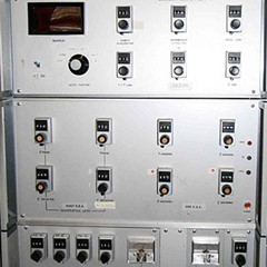
History - Electronics
A key element to the building of SHRIMP I was the design and construction of the electronics assemblies to control the instrument. At the time of construction, digital control and data acquisition was very new. In addition, the magnet field control had to be at the cutting edge to stay on top of the high resolution peaks. The electronics assemblies constructed for SHRIMP I are still largely in place today, a testament to the design skills and capabilities of the personnel of the Electronics Workshop.
History - Computer control
A new feature of SHRIMP I was the fully integrated computer control for digital data acquisition. SHRIMP I was originally controlled by an HP workstation (21MX < http://www.hpmuseum.net/exhibit.php?class=3&cat=33>) with GPIB (General Purpose Interface Bus) interfaces to the data acquisition modules. The original code was in Fortran 4. Compilation of the programs was carried out on a separate HP1000E computer, compiled and then loaded by tapes in to the 21MX. A single change to the operating program would require of the order of two hours for the loading of the new version. This was improved with the acquisition of an HP1000M system that had its own hard drive to allow the programming to be carried out directly.
The HP computer was replaced by an Apple Macintosh II in 1989. The Mac II was the first open architecture computer produced by Apple and allowed the incorporation of control boards and the use of a graphical interface. The Mac programming was carried out in C. This computer stayed in operation until 2006 despite regular shutdowns from stray discharges from the ion probe.
SHRIMP II was the first instrument to be programmed in the National Instruments LabView graphical programming language. This was initially carried out on the Macintosh computers but following National Instrument’s adoption of the Windows operating system as its standard, both SHRIMP II and SHRIMP RG computer control was changed to PC/Windows. LabVIEW operations were a factor of 2 to 4 faster on the Windows platform compared to the Mac.
The ION network was developed at RSES Electronics to interface the computers to the instrument control systems. One of the characteristics of the GPIB was the copper wire that connected all points of the instrument. This was a ready pathway for arc discharges and caused numerous failures of a variety of boards and computers, whichever was the weakest link. The ION was based on optical fibre communications and so any discharge was maintained in the box in which it occurred. Furthermore, the ION communication speed was much higher than the GPIB, and much more robust.

The SHRIMP HP-1000M computer network of ca. 1986.
History - SHRIMP I
The original SHRIMP (now called SHRIMP I) was designed and built from around 1974 to 1981. Dr Steve Clement, an ANU student who designed and built a mass spectrometer for his PhD) was recruited by Professor William Compston to produce a design for SHRIMP that enabled high mass resolution while maintaining sensitivity. The SHRIMP design was based on a published work by Professor H. Matsuda of Osaka University for a double-focussing mass spectrometer that included a quadrupole lens to minimize second order aberrations. Most of the components were manufactured in the RSES Mechanical and Electronics Workshops. SHRIMP I featured full computer control of data acquisition.
In terms of user operation, the key feature of SHRIMP was the inclusion of the Schwarzchild viewing optical system that allowed accurate placement of the primary ion beam spot on to the target. The stage was controlled by a simple joystick, and the focus was controlled manually by a simple micrometer drive. Once the sample was in focus, the spot would be seen to burn in the same place on the viewing optics monitor. The ease of operation allowed novice users to be operating the instrument independently within a few hours.
The SHRIMP I stage control was replaced by a computer-controlled version in 2006 to allow automated running from preselected points. This also saw the end of the highly reliable Apple Macintosh II computer with the incorporation of a PC running the LabVIEW software.
SHRIMP I was decommissioned in late 2010 after nearly 30 years of service. Elements of the ion optical system can be viewed in the SHRIMP laboratory.
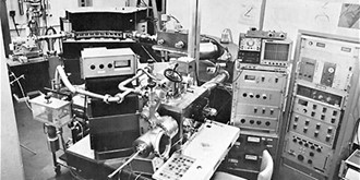
SHRIMP I as it appeared in the 1981 RSES Annual Report


